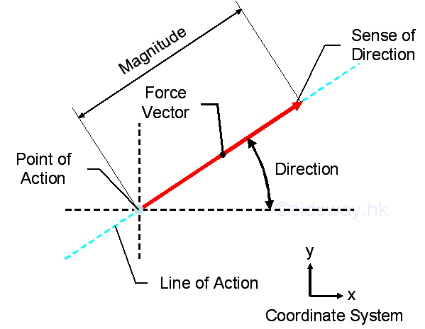
Force is the resultant of interaction between two objects in the form of
magnitude and direction at the point of interaction.
http://output.to/sideway/default.asp?qno=110400006
Force of the resultant interaction at the point of interaction can either be
combined or decomposed.
http://output.to/sideway/default.asp?qno=110400005
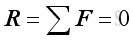
The point of interaction is in static equilibrium when the resultant forces by
Newton's first law of motion, acting on it is equal to zero.
http://www.output.to/sideway/default.asp?qno=110400006
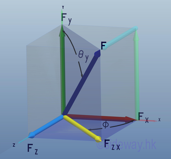
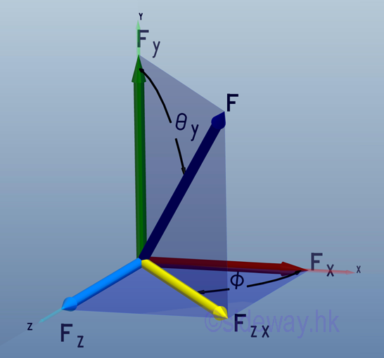
Force in a plane is just a special case of force in space with one rectangular
force vector component equal to zero.
http://www.output.to/sideway/default.asp?qno=110400005
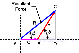
The vector representation of a force has the advantage of manipulating both the
magnitude and direction of a force at the same time trigonometrically with the
help of geometry especially in plane force manipulation.
http://www.output.to/sideway/default.asp?qno=110400006
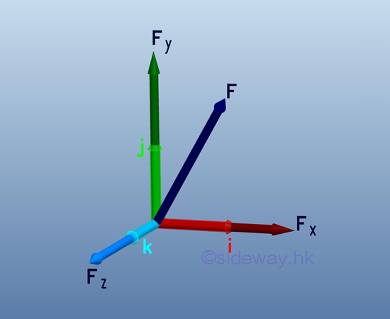
Unit vectors, i, j, and k with unit magnitude are
usually used to represent the directions of the three rectangular force vector
components of a force in space after decomposition so that forces can be
manipulated algebraically along the three axes of the coordinate system.
http://www.output.to/sideway/default.asp?qno=110400005
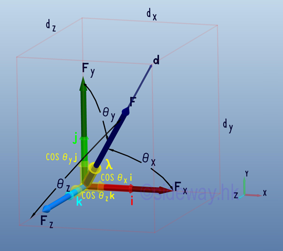
Direction cosines of a force which is equal to the cosines of θx, θy, and θz,
are just the magnitude of the three rectangular force vector components of the
unit vector λ along the force vector F and can be used to tackle problems with
angles between the force vector and coordinate axes are known.
http://www.output.to/sideway/default.asp?qno=110400005
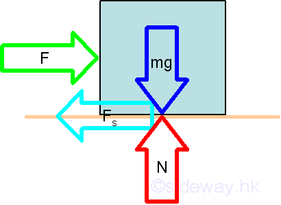
Free Body Diagram
Free body diagram is one of the common techniques used in solving engineering
mechanics statics problems by making use of the Newton's third law to isolate
the interested area from the other parts of the whole system through the
disconnection of the interaction between the interested area and the whole
system at the idealized connection points.
http://www.output.to/sideway/default.asp?qno=110100009
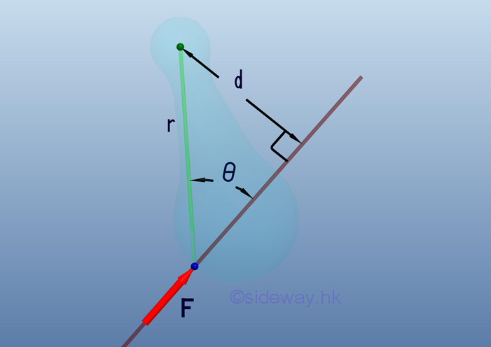
Moment of a force is the concept used to quantify the tendency to rotate an
object about a reference point as the centre of moment when forces acting on the
object are non-concurrent forces and is defined as product of force F along a
line of action and perpendicular distance d as lever arm of rotation between
line of action and point of reference, i.e. M=Fd=Frsinθ.
http://www.output.to/sideway/default.asp?qno=110100009
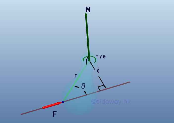
A moment vector following the right hand rule is usually used to represent the
sense and axis of moment at the interested point for the additional effect due
to a force acting on an object so that concepts of motion along the line of
force and the tendency to rotate about a point can be handled separately.
http://www.output.to/sideway/default.asp?qno=110100009
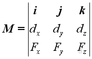
When moment is treated as a vector quantity, moment vectors itself can be
combined or decomposed through vector manipulation similar to force vector
manipulation and the moment vector of a force about a point can also be obtained
by the cross product operation of the position vector 𝐫 and the force vector
𝐅; i.e. 𝐌=𝐫⨯𝐅 or can be expressed in the determinant form.
http://www.output.to/sideway/default.asp?qno=110600002
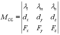
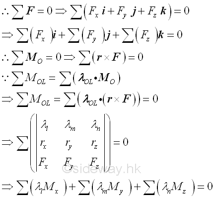
Moment about point is tendency to rotate about axis along moment vector which is
not always aligned with allowed rotation axis in practice, the moment about
specified axis can be obtained by scalar product of unit vector 𝛌 along the
specified axis passing through point O and moment 𝐌 of force 𝐅 about point O,
i.e. 𝑀=𝛌⋅𝐌=𝛌⋅(𝐫⨯𝐅). or can be expressed in determinant form.
http://www.output.to/sideway/default.asp?qno=110600003
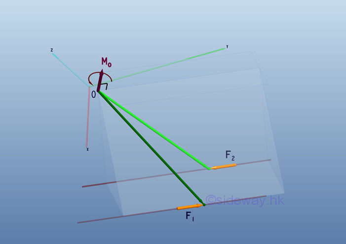
To eliminate limitations on using moment vector 𝐌 in static analysis, force
couple concept is introduced such that moment effect due to force 𝐅 at point O
is transformed into a free force couple vector of same magnitude and direction
as moment vector but independent of force 𝐅 and point O since net force of
force couple 𝐅₁𝐅₂ is zero, after translating force 𝐅 to point O.
http://www.output.to/sideway/default.asp?qno=110600005
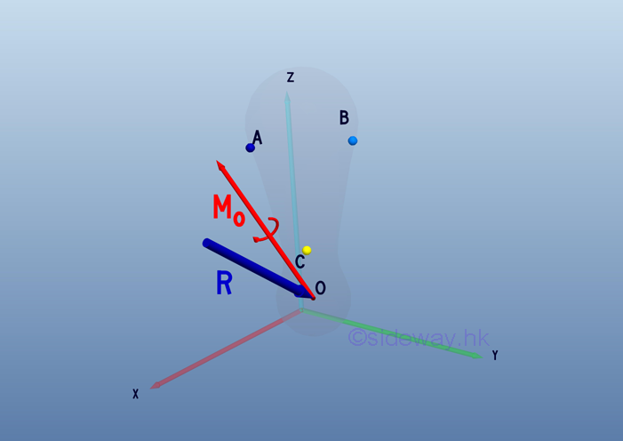
By the moment vector 𝐌 of force couple concept, system of forces acting on an
object about the interested point O can be transformed into a resultant force
vector 𝐑 by translating all forces 𝐅ᵢ to the interested point with moment
effect is replaced by a free moment vector accordingly and a resultant moment
vector 𝐌ₒ by vector addition of all free moment vectors 𝐌ᵢ.
http://www.output.to/sideway/default.asp?qno=110700013
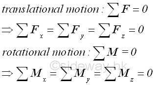
An object is therefore in static equilibrium state only when both
translational motion due to resultant force 𝐑 and rotational motion due to
resultant moment 𝐌 are equal to zero.
http://www.output.to/sideway/default.asp?qno=120200059
By making use of free body diagram technique, an object can be any part of a
mechanical system and since only six (three) equilibrium equations can be
obtained from a rigid body in three (two) dimension no more than six (three)
unknowns can be determined by the system of equilibrium equations and vector
operation is the more convenient way to determine unknowns.
http://www.output.to/sideway/default.asp?qno=120200067
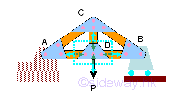
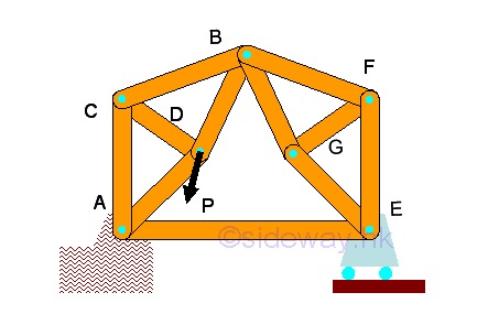
Truss is an engineering structure with members in the truss are designed for
supporting only axial loading of tensile and compressive force while bending
moment is negligible and all jointed truss members can be considered as
separated truss members with frictionless hinge pin joint as loads are always
supported by the rigid three member triangular like structure.
http://www.output.to/sideway/default.asp?qno=120200069
Besides the forces in truss, the other two main
concerns in truss design are stability and determinacy such that any unstable
member arrangement and over rigid or constrained design are eliminated in the
design.
http://www.output.to/sideway/default.asp?qno=120200071
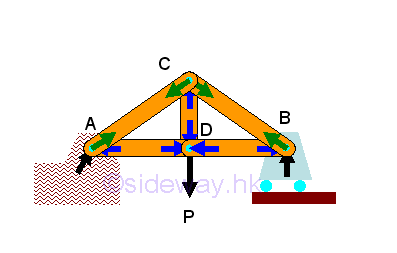
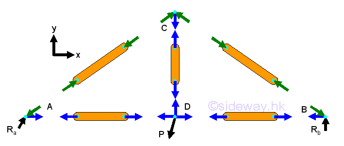
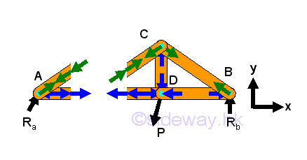
Forces in trusses can be determined by method of joints through setting up
two/three equilibrium equations for each point together with three/six static
equilibrium equations to determine unknown reactions or by constructing force
vector diagram with known forces and structure dimensions and therefore method
of joints always start with joint with two/three unknown forces.
http://www.output.to/sideway/default.asp?qno=120200072
Forces in trusses can also be determined by method of sections through setting
up three/six equilibrium equations for each virtual isolated section of truss
with unlimited shape as a rigid body together with three/six static equilibrium
equations to determine all unknown reactions and force vector diagram at joint
may provide additional equilibrium equations also.
http://www.output.to/sideway/default.asp?qno=120200074
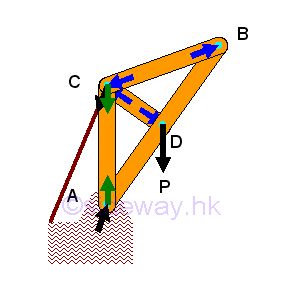
Frame is structure to support load similar to truss but with at least one
multiple force member of more than two forces and all forces acting on the
member are not along the direction of member axis and therefore unlike truss,
although forces acting upon frame member can be determined similar to force
analysis in truss, but unlike truss, moment should be considered also.
http://www.output.to/sideway/default.asp?qno=120300010
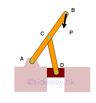
Machine is mechanical structure similar to frame but with moving component
designed to transmit and modify forces and therefore a machine is usually a
collapsible frame, but forces acting upon machine component can be determined
similar to force analysis in frame member with the consideration of force and
moment for each rigid component part.
http://www.output.to/sideway/default.asp?qno=120300017
Besides the concentrated force which is represented by a force vector, the most
common forces in practical problems are distributed forces which are either body
forces acting over a volume or surface forces acting over an area and in general
these distributed forces can also be represented by a concentrated force through
system of forces transformation.
http://www.output.to/sideway/default.asp?qno=120300021
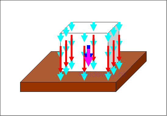
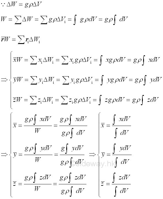
Body Forces
Weight of a rigid object which can be considered as distributed body forces 𝐖ᵢ
of infinitesimal element over a volume, can be represented by a single force 𝐖
through system of forces transformation and determined by equating the two
systems of forces where the location of force is called centre of gravity which
is same as the centroid of volume for a homogeneous body.
http://www.output.to/sideway/default.asp?qno=120600009
Surface Forces
Similarly body dead load acting on a surface can be considered as distributed
surface forces 𝐖ᵢ of infinitesimal element over surface normally which can be
represented by a single force 𝐖 through system of forces transformation and
determined by equating two systems of forces where location of force for a
homogeneous distributed load depending on shape of load only.
http://www.output.to/sideway/default.asp?qno=120700005
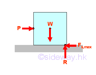
Besides distributed normal or inclined surface forces, friction force due to the
relative lateral motion of two contact surfaces is a common distributed
tangential surface force found in practical engineering problems and maximum
static friction force which is proportional to the normal applied force can be
developed when two surfaces are impending.
http://www.output.to/sideway/default.asp?qno=120700007
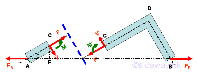
When a member of an rigid body is in static equilibrium, the internal forces in
the member tending to resist those external forces should be in equilibrium
similar to the structure analysis by section also but the internal force should
be represented by a force-couple system instead of a force vector system since
shear forces and bending moments are usually involved.
http://www.output.to/sideway/default.asp?qno=120800020
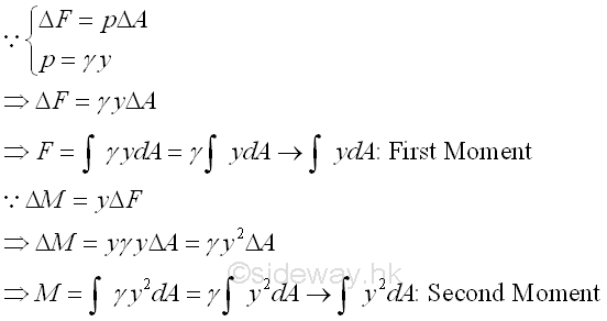
In general, second moment of a body about a reference is the summation of moment
of distributed forces of intensity proportional to the distance between force
and reference over the body relating to the square or second order of distance
and shape of the body only while first moment of a body about a reference is
relating to the distance and shape of the body only.
http://www.output.to/sideway/default.asp?qno=121000001
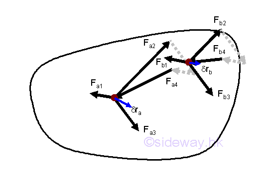
When a body in static equilibrium, since all forces are in equilibrium and the
resultant force on any particle is equal to zero, the work done by the resultant
force is equal to zero also and therefore the work done on the particle for any
virtual displacement δs is equal to zero as the resultant force acting on a
particle is zero.
http://www.output.to/sideway/default.asp?qno=121100089


 Nu Html Checker
  na
na