TOCForceMomentCoupleSystem of ForcesStatic EquilibriumStructure AnalysisDistributed ForceFriction Force Draft for Information Only
Content
Internal Forces
in Beams
Internal Forces in BeamsBeam is one of the most common structure member used in structure for supporting vertical loads which are perpendicular to the axis of the beam. Usually the axial forces of internal forces along the axis of the beam can be ignored as there is either no horizontal load acting on the beam or the horizontal loads can be neglected. Therefore, the internal forces in beam are shear and bending memont only. However, when the applied forces to the beam is not perpendicularl to the the axis of the beam, the internal axial forces should also be considered. Shear and Bending Moment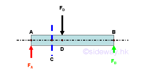
Consider there is only vertical loading acting on a long straight prismatic bar with uniform cross-sectional area throughout the beam length, the equilibrium equations are 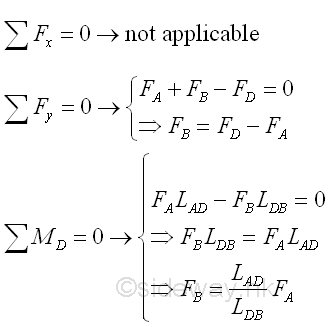
Since there is no axial force in the beam, the internal forces in a beam is shear and bending moment. 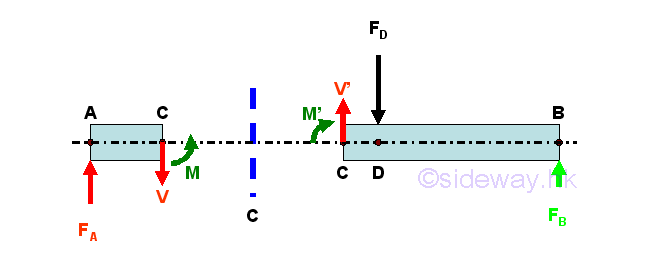
Consider the member section AC of length LAC, the internal forces at point C are 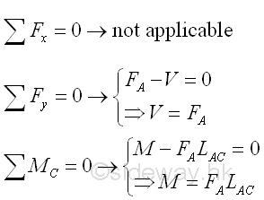
Conventions of Internal ForcesIn general, the length, measured from point A on the left to point C on the right, is considered as a positive length, the external applied force FA, pointing upward is also considered as a force in positive sense and the produced moment due to the external force FA about point C is in negative sense. The direction of internal forces at point C of beam section AC can then be defined by assuming the beam section AC is fixed at pont C. Therefore the positive signed shear V of negative sense in downward direction and the positive signed bending moment M of positive sense in anticlockwise direction are directed at point C of the beam section AC. And the internal forces at point C of the beam section CB can then be defined as internal force of equal in magnitude and opposite in sense using the equilibrium equations at point C of an beam AB in equilibrium or by direct calculation thruough setting up equilibrium equations of beam section CB. According to the convention of the internal forces used in the free body diagrams, the calculated values from the two free body beam sections are the same for the internal forces, since the senses of the internal forces are represented by the standard conventions used in the free body diagrams, i.e. a positive calculated values implies correct sign conventions used in both free body diagrams and a negative calculated value implies incorrect sign conventions used in both free body diagrams, but internal forces in both force diagrams are still equal in magnitude but opposite in sense. Imply 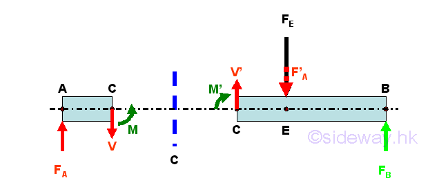
Types of Beam SupportsThere are several common types of support used in beam design for engineering structure design. The beam supports are Hinged Support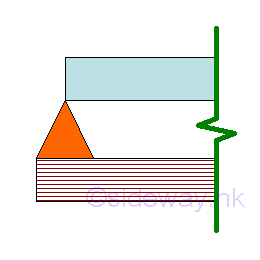
A hinged support is a simple end support at an end of a beam at which there may be slope, but no displacement is allowed. Roller Support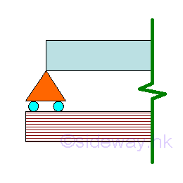
A roller support is a simple end support at an end of a beam at which there may be slope, but no displacement is allowed. Fixed Support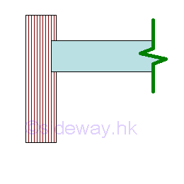
A fixed support is an fixed end support at an end of a beam at which no slope and no displacement is allowed. Free End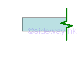
A free end does not have any support or constraint at an end of a beam at which both slope and displacement is allowed. Interior Support
An interior support can be a hinged or roller support located between ends of a beam at which slope is continuous from one side of the support to the other, but no displacement is allowed. Intenal Hinge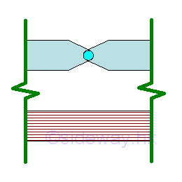
An intenal hinge is a hinge linkage located between ends of two separate beams at which there may be discontinuous slope from one side of the hinge linkage to the other, and the allowed displacement on both sides of the hinge linkage separating the two beams is continuous. Types of BeamsBeam can be named according to how the beam is supported. The distance L between two supports is the span of the beam for supporting loads. The common types of beams are Simply Supported Beam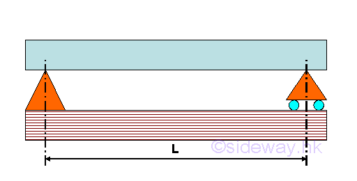
A simply supported beam is supported by a hinged support at one end of the beam and a roller support at another end of the beam. Overhanging Beam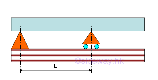
A overhanging beam is supported by a hinged support (or roller support) at one end of the beam and a roller support (or hinged support) at the another side of the beam which is located away from the another end of the beam. Cantilever Beam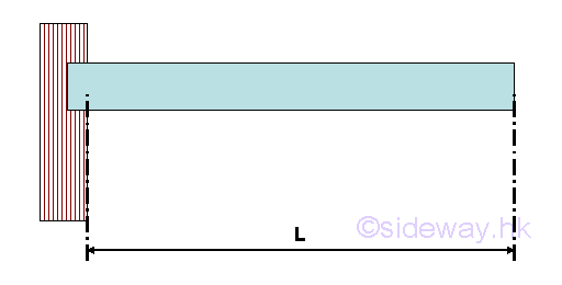
A cantilever beam is supported by a single fixed support at one end of the beam only and the another end of the beam there is a free end without any support or constraint. Continuous Beam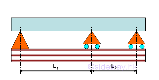
A continuous beam is supported by more than two supports along the length of a beam. In general, a continuous beam is supported by a hinged support at one end of the beam, a roller support at another end of the beam, and one or more roller supports are used between the two end supports. Fixed Beam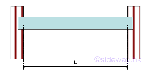
A fixed beam is supported by two fixed supports at both ends of the beam. Cantilever with simply supported Beam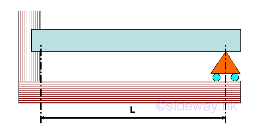
A cantilever with simply supported beam is supported by a fixed supports at one end of the beam and a roller support at another end of the beam. Hinge Connected BeamsHinge connected beams is a single continuous structure by connecting two or more different kinds of supported beams end to end together by hinges. For example, a hinge connected beam with simply support beams connected by internal hinge 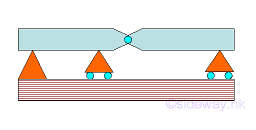
Or, a hinge connected beam with fixed beam and simply support beam connected by internal hinge 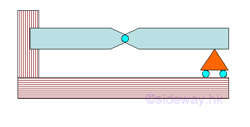
Loads and ReactionsLoads are applied along the span of a beam. In general, the loads considered in static are the concentrated load P and distributed load W. Concentrated load is the one which can be considered as acting at a point although the load is distributed over a small length of the beam in practice. Distributed load is the one which can not be considered as acting at a point because the load is spread over a considerable length of the beam. The distributed load is usually expressed as load w per unit length. The distributed load is called uniformly distributed load when the load w per unit length is a constant or uniform from point to point over the lengh of load distributed. And those distributed loads with varying loading from point to point over the lengh of load distributed are grouped as varying distributed load, e.g linear varying distributed load. 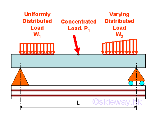
Supports commonly used for the support and connection of beams are the hinged support, roller support, fixed support, and the internal hinge connection. If the total unknown reactions involved in all supports are three unknowns only, the reactions will be statically determinate. Therefore, simply supported beam, overhanging beam and cantilever beam are statically determinate beams. If the total unknown reactions involved in all supports are more than three unknowns, the reactions will be statically inderterminate. Since only three unknowns can be determined by static methods, methods of statics is not sufficient to determine the reactions. Therefore, continuous beam, fixed beam and cantilever with simply supported beam are statically indetermine beams. In order to determine the reactions for statically indetermine beams, additional equations can be taken from the relationships based on the properties of the beam and the resistance to bending under the applied loads. If there are totally only two unknown reactions involved in all supports, the beam is not stable for any applied loads and the beam is partially constrained only. Therefore beam supported by two rollers is partitally constrained. The beam is stable when the applied loads is vertical and the beam will move when the horizotal components of the applied loads is not equal to zero. Therefore in practice, a horizontal restraint is usually used in one support to restrain the beam from rotating or moving horizontal. ©sideway ID: 120800022 Last Updated: 8/24/2012 Revision: 0 Ref: References
Latest Updated Links
  Nu Html Checker Nu Html Checker  na na |
 Home 5 Business Management HBR 3 Information Recreation Hobbies 9 Culture Chinese 1097 English 339 Travel 45 Reference 79 Hardware 55 Computer Hardware 263 Software Application 213 Digitization 37 Latex 52 Manim 205 KB 1 Numeric 19 Programming Web 289 Unicode 504 HTML 66 CSS 65 SVG 46 ASP.NET 270 OS 431 DeskTop 7 Python 72 Knowledge Mathematics Formulas 8 Set 1 Logic 1 Algebra 84 Number Theory 206 Trigonometry 31 Geometry 34 Calculus 67 Engineering Tables 8 Mechanical Rigid Bodies Statics 92 Dynamics 37 Fluid 5 Control Acoustics 19 Natural Sciences Matter 1 Electric 27 Biology 1 |
Copyright © 2000-2026 Sideway . All rights reserved Disclaimers last modified on 06 September 2019
 or
or