TOCForceMomentCoupleSystem of ForcesStatic EquilibriumStructure AnalysisDistributed ForceFriction Force Draft for Information Only
Content
Construction of
Shear Diagram & Bending Moment Diagram
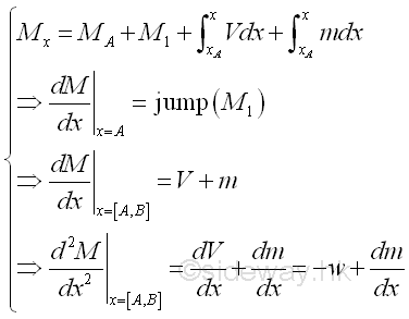
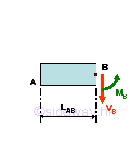
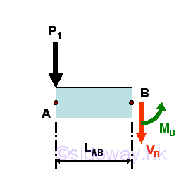
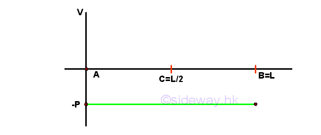
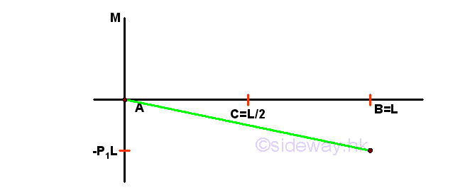
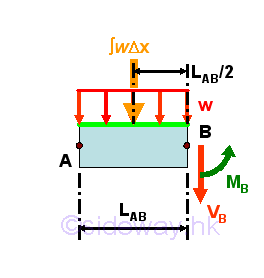
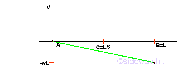
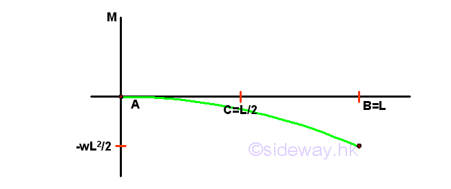
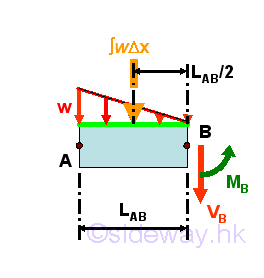
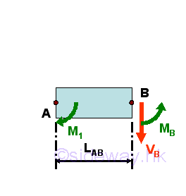
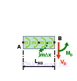
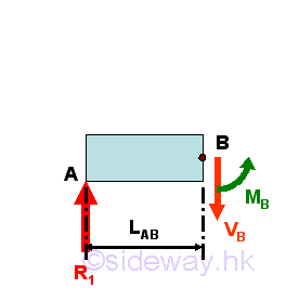
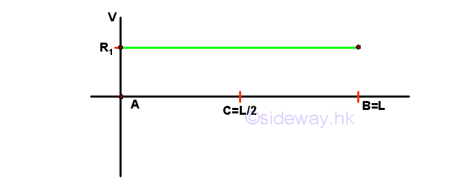
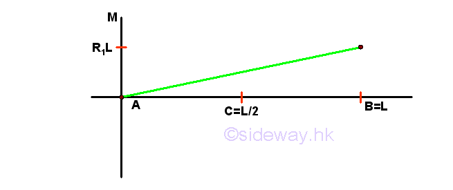
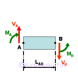
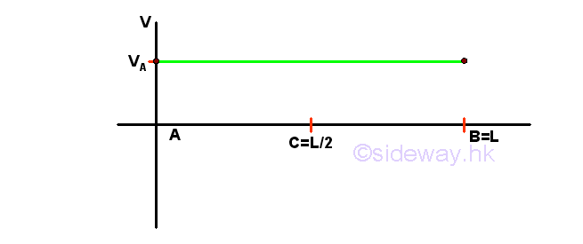
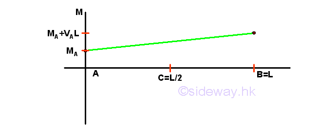
Construction of Shear Diagram & Bending Moment DiagramConsider a general beam segment AB 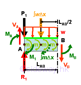
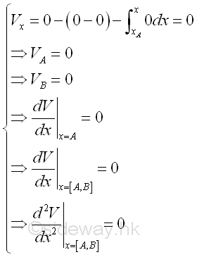
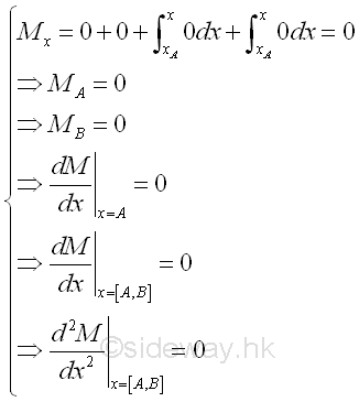
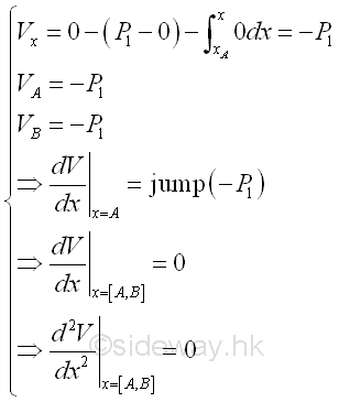
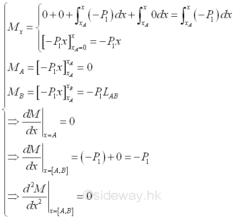
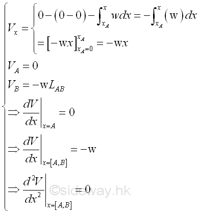
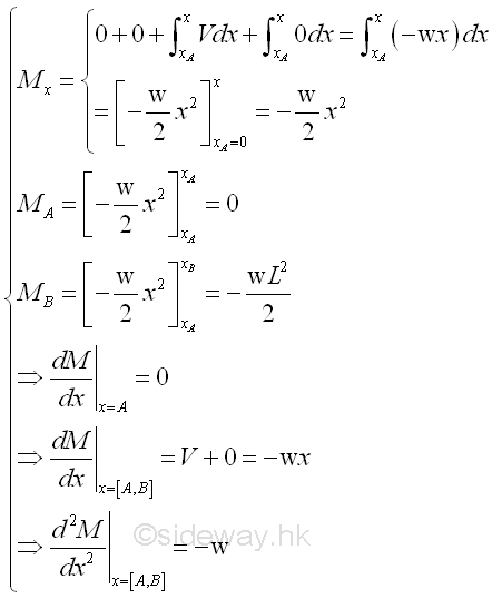
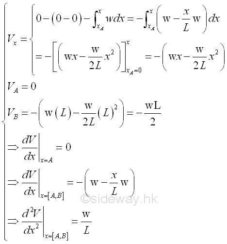
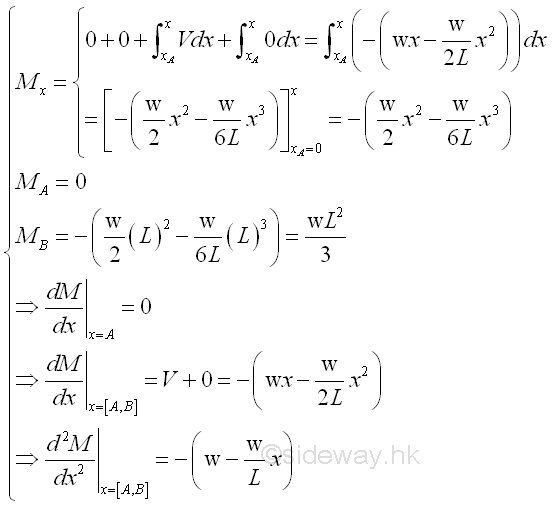
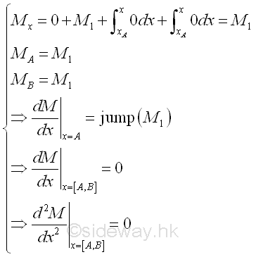
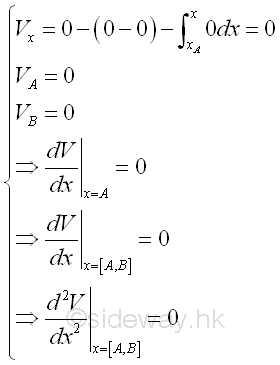
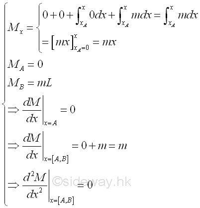
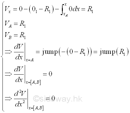
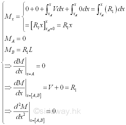
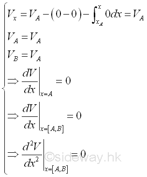
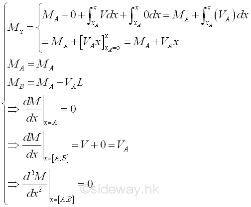
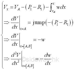
Relations derived from the equilibrium equations are.
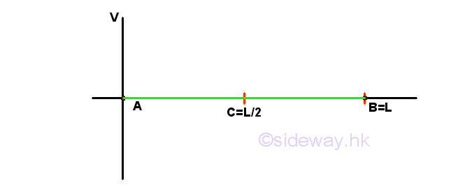
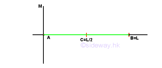
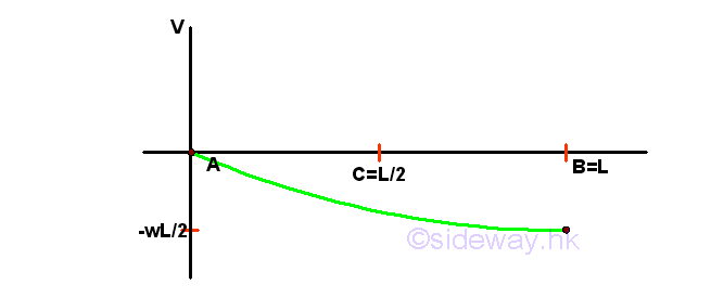
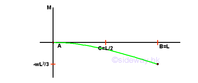
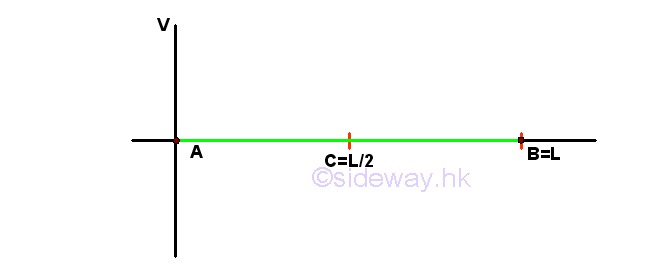
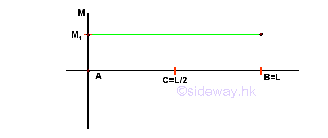
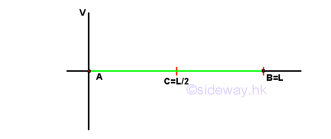
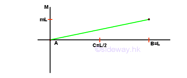
The equations of shear and bending moment in the beam derived from a beam segment AB can be used for constructing the shear diagram and bending moment diagram. These equations can be applied for beam segment with any type of loading by setting the corresponding loads to zero when these loads are not available. Start drawing the shear diagram and bending moment diagram from left end to right end. And the considered beam segment is assumed to be fixed at the rightmost edge of the beam segment considered and the load applied on the rightmost edge of the beam segment is ignored as usual. Summary of stability and determinacy of planar truss:
©sideway ID: 120900010 Last Updated: 9/28/2012 Revision: 0 Ref: References
Latest Updated Links
  Nu Html Checker Nu Html Checker  na na |
 Home 5 Business Management HBR 3 Information Recreation Hobbies 9 Culture Chinese 1097 English 339 Travel 45 Reference 79 Hardware 55 Computer Hardware 261 Software Application 213 Digitization 37 Latex 52 Manim 205 KB 1 Numeric 19 Programming Web 289 Unicode 504 HTML 66 CSS 65 SVG 46 ASP.NET 270 OS 431 DeskTop 7 Python 72 Knowledge Mathematics Formulas 8 Set 1 Logic 1 Algebra 84 Number Theory 206 Trigonometry 31 Geometry 34 Calculus 67 Engineering Tables 8 Mechanical Rigid Bodies Statics 92 Dynamics 37 Fluid 5 Control Acoustics 19 Natural Sciences Matter 1 Electric 27 Biology 1 |
Copyright © 2000-2026 Sideway . All rights reserved Disclaimers last modified on 06 September 2019
 and
and