
TOCForceMomentCoupleSystem of ForcesStatic EquilibriumStructure AnalysisDistributed ForceFriction Force Draft for Information Only
Content
Internal Forces
in Beams
Internal Forces in BeamsThe shearing forces and bending moments in a statically determinate beam can be determined by the equilibrium equations. Using the standard convention, the distribution of internal forces in a beam can be represented graphically by plotting the values of shear or bending moment against the distance from one end of the beam. Shear and Bending Moment DiagramsInternal Forces in a Cantilever Beam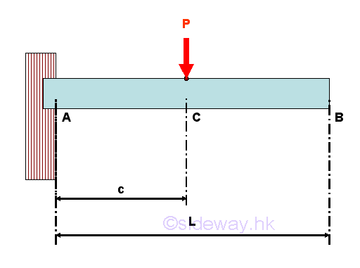
For example, consider a simple cantilevel beam with one applied load applied around the middle of the beam. The free-body diagram of the entire beam is 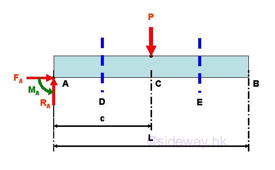
The reactions at the fixed support can be determined by the equilibrium equations. 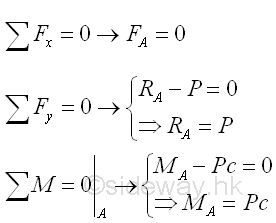
Internal forces can be determined by dividing the beam into two separated free body. Selecting a point D between A and C, i.e. A<D<C 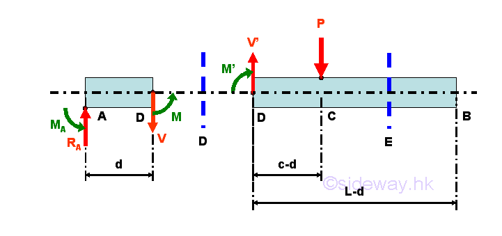
Consider the member section AD of length d, the internal forces at point D are 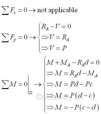
Point D is a random point between A and C. The shear force V is a constant and is equal to P between point A and point D. And bending moment M is a linear function of point D. Therefore bending moment M=-Pc at point A and bending moment M=0 at point C. Selecting another point E between C and B, i.e. C<E<B 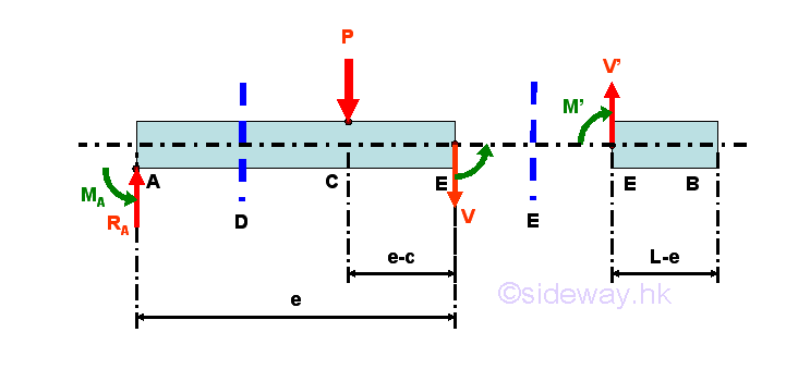
Consider the member section EB of length L-e, the internal forces at point E are 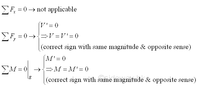
Point E is a random point between C and B. Both the shear force V and bending moment M is equal to zero between point C and point B. Shear Diagram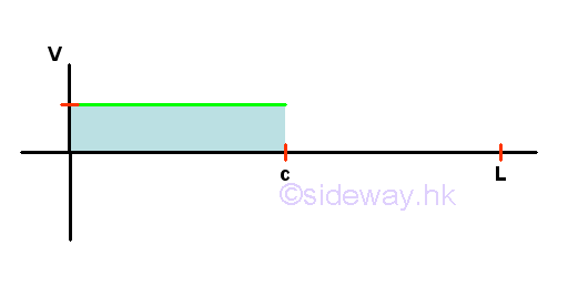
Bending Moment Diagram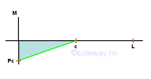
Internal Forces in a Simply Supported Beam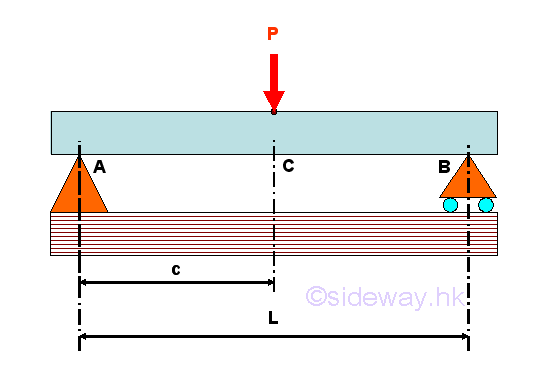
For example, consider a simply supported beam with one applied load applied around the middle of the beam. The free-body diagram of the entire beam is 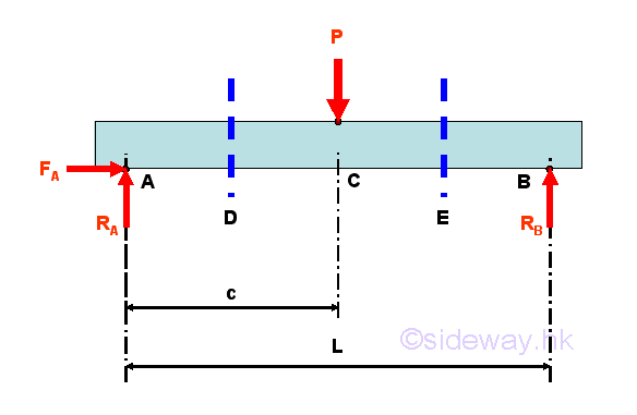
The reactions at the hinged and roller supports can be determined by the equilibrium equations. 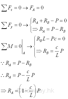
Internal forces can be determined by dividing the beam into two separated free body. Selecting a point D between A and C, i.e. A<D<C 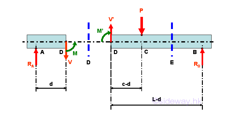
Consider the member section AD of length d, the internal forces at point D are 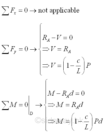
Point D is a random point between A and C. The shear force V is a constant and is equal to (1-c/L)P between point A and point C. And bending moment M is a linear function of point D. Therefore bending moment M=0 at point A and bending moment M=(1-c/L)Pc at point C. Selecting another point E between C and B, i.e. C<E<B 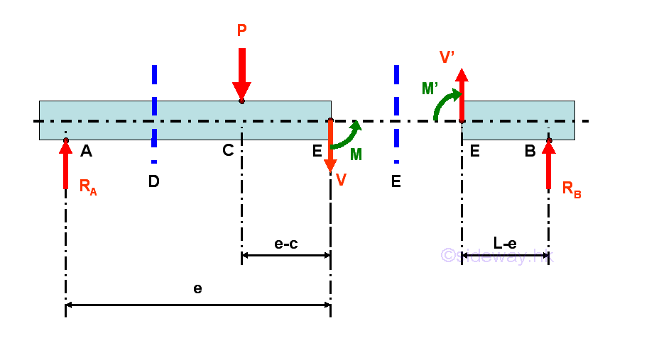
Consider the member section EB of length L-e, the internal forces at point E are 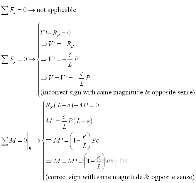
Point E is a random point between C and B. The shear force V is a constant and is equal to -(c/L)P between point C and point B. And bending moment M is a linear function of point E. Therefore bending moment M=(1-c/L)Pc at point C and bending moment M=0 at point B Shear Diagram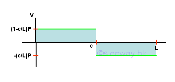
Bending Moment Diagram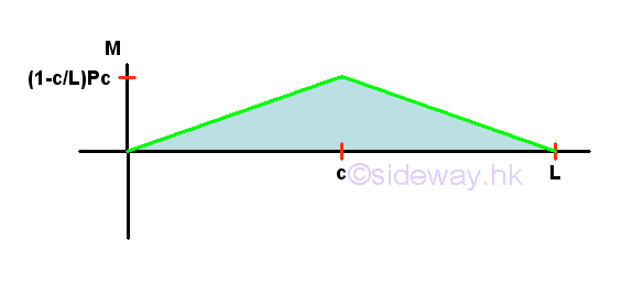
Internal Forces in a Overhanging Beam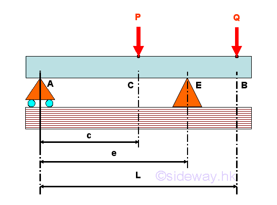
For example, consider a overhanging beam with two applied load applied around the middle and the free end of the beam. The free-body diagram of the entire beam is 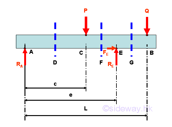
The reactions at the roller and hinged supports can be determined by the equilibrium equations. 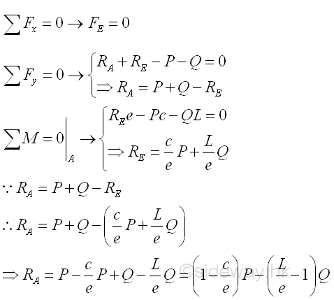
Internal forces can be determined by dividing the beam into two separated free body. Selecting a point D between A and C, i.e. A<D<C 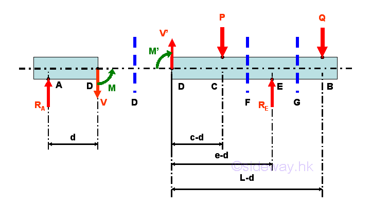
Consider the member section AD of length d, the internal forces at point D are 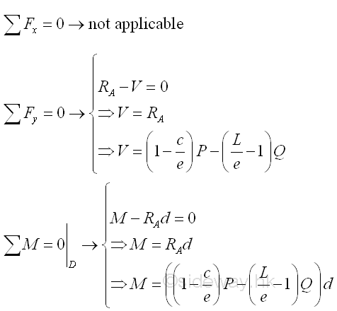
Point D is a random point between A and C. The shear force V is a constant and is equal to ((1-c/e)P-(L/e-1)Q) between point A and point C. And bending moment M is a linear function of point D. Therefore bending moment M=0 at point A and bending moment M=((1-c/e)P-(L/e-1)Q)c at point C. Selecting another point F between C and E, i.e. C<F<E 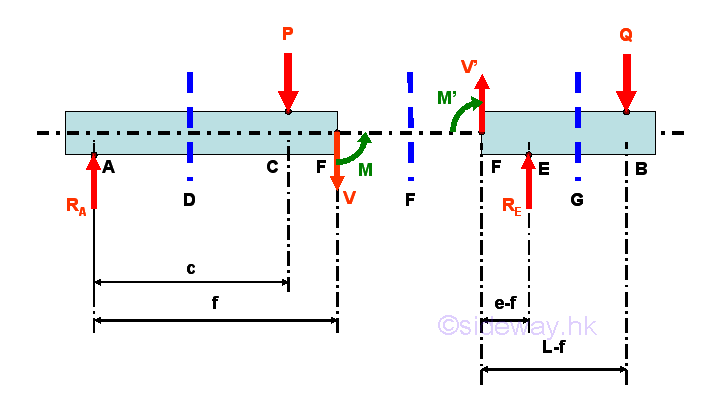
Consider the member section AF of length f, the internal forces at point F are 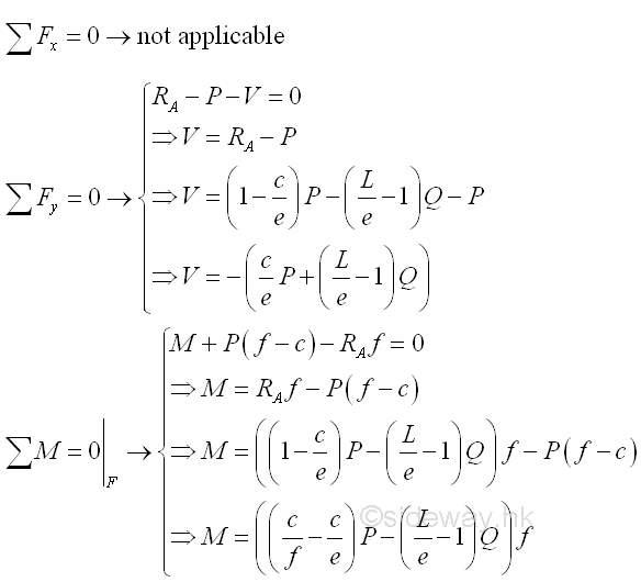
Point F is a random point between C and E. The shear force V is a constant and is equal to (-(c/e)P-(L/e-1)Q) between point C and point E. And bending moment M is a linear function of point F. Therefore bending moment M=((1-c/e)P-(L/e-1)Q)c at point C and bending moment M=-Q(L-e) at point E. Selecting another point G between E and B, i.e. E<G<B 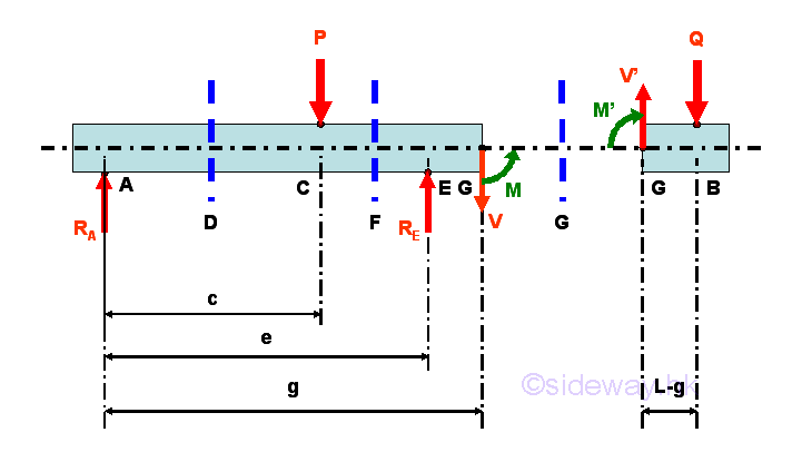
Consider the member section GB of length L-g, the internal forces at point G are 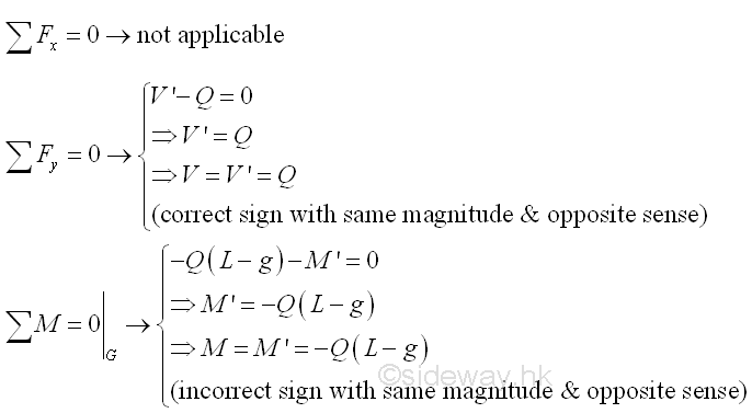
Point G is a random point between E and B. The shear force V is a constant and is equal to Q between point E and point G. And bending moment M is a linear function of point G. Therefore bending moment M=-Q(L-e) at point E and bending moment M=0 at point B. Assumption for Shear and Bending Moment DiagramsSince length L is greater than length e, the reaction force RA at point A may be negative if load Q term is greater than load P term. For normal practical applications, the reaction force RA at point A is usually pointing upward. Therefore, the reaction force RA at point A is assumed positive in plotting the shear and bending moment diagrams. 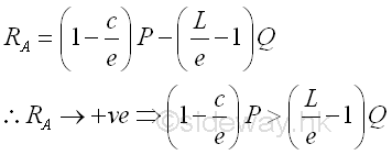
Shear Diagram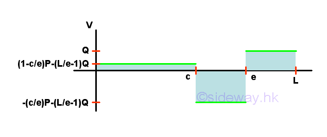
Bending Moment Diagram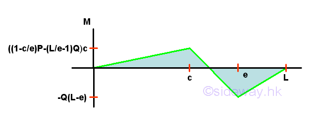
©sideway ID: 120800023 Last Updated: 8/29/2012 Revision: 0 Ref: References
Latest Updated Links
  Nu Html Checker Nu Html Checker  na na |
 Home 5 Business Management HBR 3 Information Recreation Hobbies 9 Culture Chinese 1097 English 339 Travel 45 Reference 79 Hardware 55 Computer Hardware 263 Software Application 213 Digitization 37 Latex 52 Manim 205 KB 1 Numeric 19 Programming Web 289 Unicode 504 HTML 66 CSS 65 SVG 46 ASP.NET 270 OS 431 DeskTop 7 Python 72 Knowledge Mathematics Formulas 8 Set 1 Logic 1 Algebra 84 Number Theory 206 Trigonometry 31 Geometry 34 Calculus 67 Engineering Tables 8 Mechanical Rigid Bodies Statics 92 Dynamics 37 Fluid 5 Control Acoustics 19 Natural Sciences Matter 1 Electric 27 Biology 1 |
Copyright © 2000-2026 Sideway . All rights reserved Disclaimers last modified on 06 September 2019