
TOCForceMomentCoupleSystem of ForcesStatic EquilibriumStructure AnalysisDistributed ForceFriction Force Draft for Information Only
Content
Internal Forces
in Beams
Internal Forces in BeamsThe shearing forces and bending moments due to distributed load in a statically determinate beam can also be determined by the equilibrium equations also. Using the standard convention, the distribution of internal forces in a beam can be represented graphically by plotting the values of shear or bending moment against the distance from one end of the beam. The problem of using the equilibrium equations to determine the values of internal forces in a beam with distributed load is similar to that with concentrated loads. Since both shear and bending moment in the beam is created by the applied load, relations among load, shear and bending can be used to develope formulas for calculating load, shear and bending moment in the beam. As distributed load can be represented by an equivalent concentrated load, the relations can be developed in a similar way. Relations among Load, Shear and Bending MomentDistributed LoadFor example, ignoring the horizontal forces, dividing a simply supported beam with variable distributed load w(x) per unit length into three imaginary beam sections. 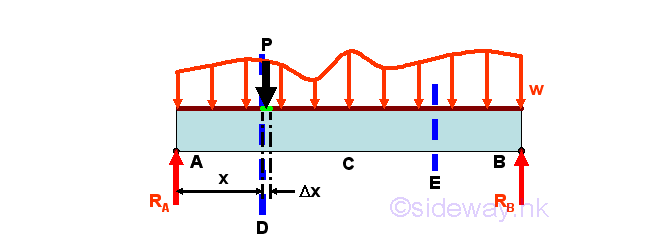
Since a concentrated load P can be considered as a distributed force over an infinitely small length Δx of the beam, a distributed load over an infinitely small length Δx may also be considered as concentrated forces of variable intensity w(x) per unit length spread over the beam by neglecting the small variation Δw. Therefore the relations among load, shear and bending moment of a distributed load can be determined by the evaluation of an infinitesimal beam element under loading. Consider the free body diagram of an infinitesimal beam element of length Δx under the variable distributed load w(x). The total distributed load acting on the infinitesimal beam element is approximately equal to wΔx. Assuming the shear difference between the ends of the infinitesimal beam element is ΔV. And assuming the bending moment difference between the ends of the rigid infinitesimal beam element is ΔM. Imply 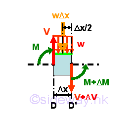
Relation between Distributed Load and ShearSimilar to concentrated load, the relation between distributed load and shear can be determined by setting equilibrium equation of the vertical components of forces acting on the infinitesimal beam element. Imply 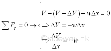
When taking the limit as Δx tends to zero, the function ΔV/Δx can therefore be interpreted as the derivative of the shear V with respect to x. Imply 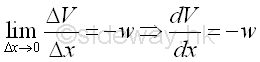
According to the derivative, the slope of the shear curve V(x) is negative, i.e. slope is decreasing, since the load per unit length is usually point downward in positive sign. And the derivative of the shear curve V(x) with respectie to x is therefore equal to the negative sense of the load per unit length at point x. And the shear difference between point D and point E can then be determined by integration. Imply 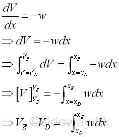
Therefore the shear difference between point D and point E is also equal to the negative sense of the total signed area under the loading curve of the applied distributed load between point D and point E. However, concentrated loads cannot be considered together with distributed loads, since when a concentrated load is applied at a point between point D and point E, the shear curve will be discontinuous at that point and the formula obtained by integration becomes invalid. Therefore the shear difference due to distributed load can only be considered between two successive concentrated loads and the shear difference due to all concentrated loads are considered separately. Relation between Shear due to Distributed Load and Bending MomentSimilarly, the relation between shear due to distributed load and bending moment can be determined by setting equilibrium equation of the bending moment of forces about point D' on the right hand side of the infinitesimal beam element . Imply 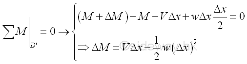
When Δx approachs zero, the term w(Δx)^2/2 is a small quantity of the second order and can be neglected. 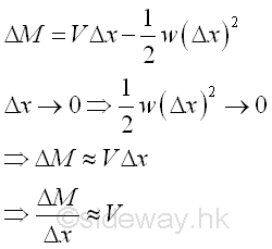
When taking the limit as Δx tends to zero, the function ΔM/Δx can therefore be interpreted as the derivative of the bending moment M with respect to x. Imply 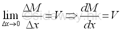
According to the derivative, the slope of the bending moment curve M(x) is equal to the value of shear. And the derivative of the shear curve V(x) with respectie to x is therefore equal to the same sense of the shear at point x at which no concentrated load is applied. Since the maximum bending moment of the bending moment curve M(x) is located at the derivative equals to zero, Therefore the maximum bending moment can be found at shear V(x) is equal to zero. And the bending moment difference between point D and point E can then be determined by integration. Imply 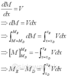
Therefore the bending moment difference between point D and point E is also equal to the same sense of the total signed area under the shear curve due to the applied distributed load between between point D and point E. Although concentrated loads is not considered together with distributed loads to determine the shear function because of the discontinuity of shear curve at a point caused by the concentrated load applied at the point between point D and point E. However, if the bending moment difference equation or the shear curve is corrected according to the additional of concentrated loads, the corrected bending moment difference equations are still valid. Therefore in order to prevent extra work, the bending moment difference due to distributed load is usually considered between two successive concentrated loads and the shear difference due to all concntrated loads are considered separately and the shear curve is corrected accordingly. But, the bending moment difference equation will become invalid when a couple is applied at a point beween point D and point E, because the sudden change in bending moment caused by a couple will create a shear in the beam also. Both the additional shear and bending moment are not considered by both the shear difference and bending moment difference equations. Simply Supported Beam with Unformly Distributed Load ExampleFor example, ignoring the horizontal forces, a simply supported beam with uniformly distributed load of w per unit length over the span LAB of the beam. 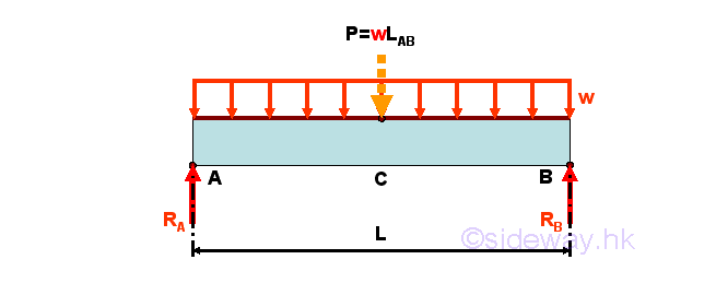
For an uniformly distributed load of w per unit length over the span LAB of the beam, the uniformly distributed load can be represented by an equivalent concentrated force of wLAB acting at the centroid of the distributed load, i.e. the middle point of point A and point B, on the simply supported beam. The Reaction forces can be determined by setting up the equilibrium equations. Imply 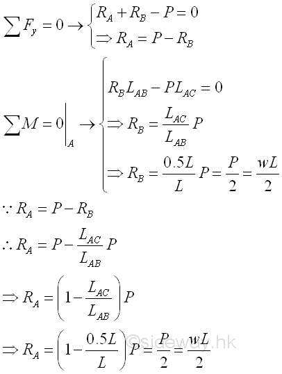
External Loads DiagramFor determining the internal forces in beam, the first step is to prepare the curve of external loads, concentrated loads, distributed load, and bending moment and couple. One of the important points in plotting external loads diagram, shear curve and bending moment curve is that all curves are plotted according to the correctness of the forces comparing with the standard convention, not the sense of the forces. Therefore, both concentrated forces RA and RB are negative sign of incorrect sense. And the distributed load over the span of beam AB is positive sign of correct sens. Imply 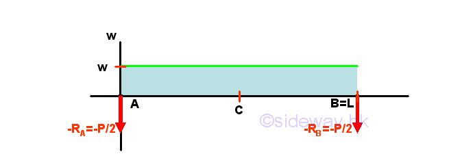
Shear DiagramIn determining the internal force, shear, in beam, the key concern is the locations of external forces. As there are only two external forces at the end of the span of the beam and one distributed load spread over the whole span of beam, the beam can be treated as one imaginary beam section. The two sets of equations for calculating the internal force, shear are 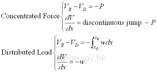
Start drawing the shear diagram from point A at the left side of the beam and begin with the concentrated force -RA at point A in the external loads diagram. Assume point A' is the right hand side of the infinitesimal beam element section AA'. Imply 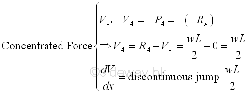
The shear is equal to wL/2 at point A' as shear at point A is equal zero. The slope of the shear curve of the infinitesimal beam element section AA' is equal to a vertical slope, a discontinuous jump wL/2, i.e. a point at point A'. In other words, there is a discontinous step change at point A. Then the distributed load w per unit length over length A'B' in the external loads diagram of the beam section A'B'. Imply 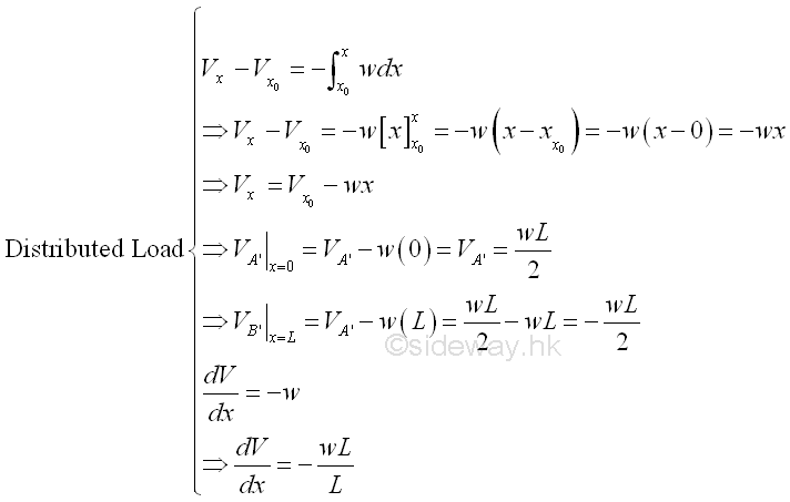
The shear curve is a oblique straight line with slope -w. The straight line is equal to wL/2 at point A' and is equal to -wL/2 at point B'. Finally the concentrated force -RB at point B in the external loads diagram. Since point B is the assumed fixed point at the rightmost edge of the beam considered, according to the Newton's third Law, i.e action and reaction forces are equal and opposite, the fixing force provided by the concentrated force RB should be equal in magnitude and opposite in sense to the shear force of the left hand side. Or the shear force VB should equal to the value of external concentrated force, -RB at point B in the external loads diagram. Imply 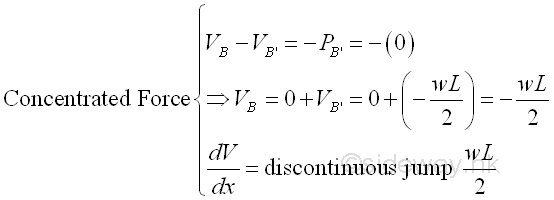
The shear is equal to -wL/2 at point B as external force at point A is ignored, i.e. equal to zero. The slope of the shear curve of the infinitesimal beam element section B'B is equal to a vertical slope, a discontinuous jump wL/2, i.e. a point at point B. In other words, there is a discontinous step change at point B. The shear diagram is 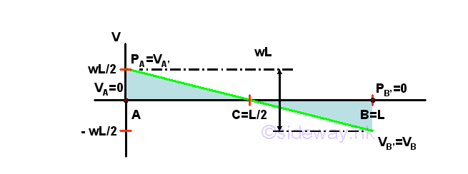
Bending Moment DiagramIn determining the internal force, bending moment, in beam, the key concern is also the locations of external forces. As there are only two external forces at the end of the span of the beam and one distributed load spread over the whole span of beam, the beam can be treated as one imaginary beam section. The two sets of equations for calculating the internal force, bending moment are 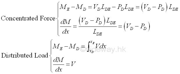
Start drawing the bending moment diagram from point A at the left side of the beam and begin with all forces VA-(-RA) at point A. Assume point A' is the right hand side of the infinitesimal beam element section AA'. Imply 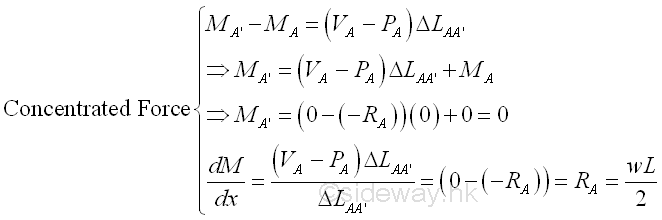
The bending moment is equal to zero at point A' as bending moment at point A is equal zero and moment arm of a infinitesimal beam element section tends to zero also. The slope of the bending moment curve of the infinitesimal beam element section AA' is equal to wL/2. Then the distributed load w per unit length over length A'B' in the external loads diagram of the beam section A'B'. Imply 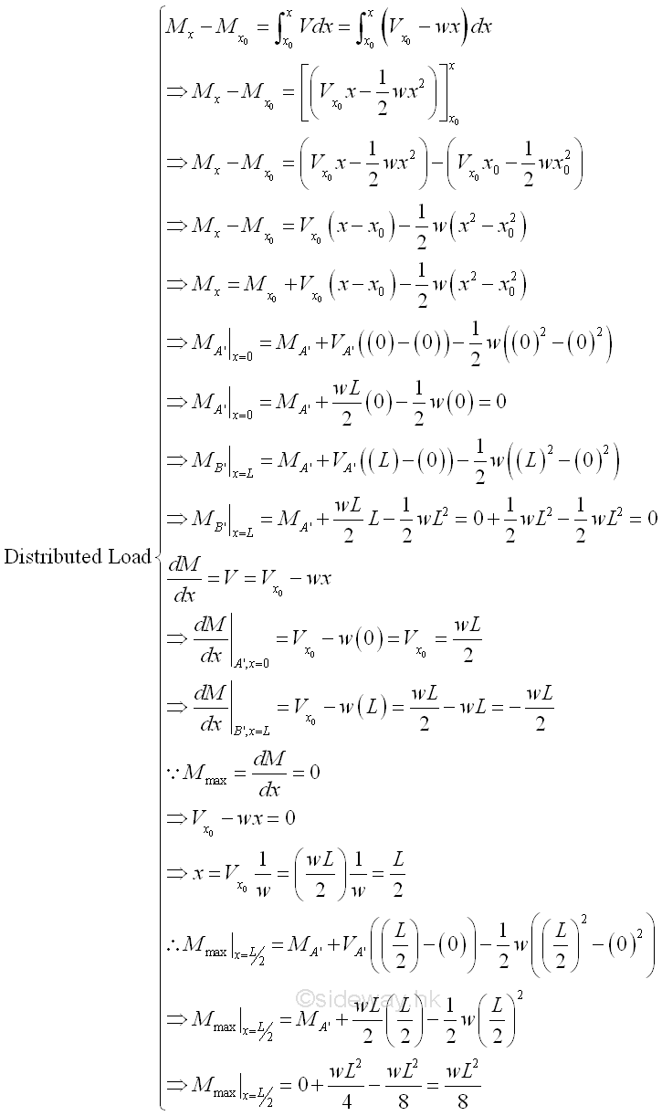
The bending moment curve is a curve of the second degree with maximum bending moment of wL^2/8 at position L/2, i.e. point C. And both the bending moments at point A' and point B' are equal to zero. But the slope of bending moment curve at point A' is wL/2 and the slope of the bending moment curve at point B' is -wL/2. Finally the concentrated force -RB at point B in the external loads diagram. Since point B is the assumed fixed point at the rightmost edge of the beam considered, according to the Newton's third Law, i.e action and reaction forces are equal and opposite, the fixing force provided by the concentrated force RB should be equal in magnitude and opposite in sense to the shear force of the left hand side. Or the shear force VB should equal to the value of external concentrated force, -RB at point B in the external loads diagram. Imply 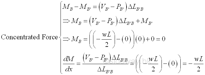
The bending moment is equal to zero at point B' as bending moment at point A is equal zero and moment arm of a infinitesimal beam element section tends to zero also. The slope of the bending moment curve of the infinitesimal beam element section AA' is equal to wL/2. The bending moment diagram is 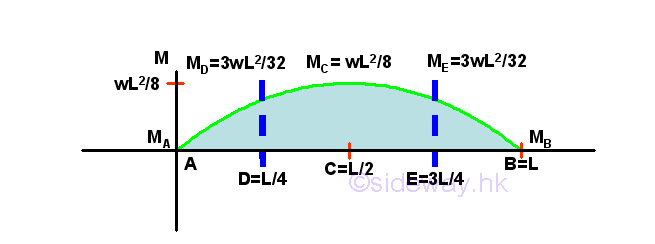
©sideway ID: 120900002 Last Updated: 9/24/2012 Revision: 1 Ref: References
Latest Updated Links
  Nu Html Checker Nu Html Checker  na na |
 Home 5 Business Management HBR 3 Information Recreation Hobbies 9 Culture Chinese 1097 English 339 Travel 45 Reference 79 Hardware 55 Computer Hardware 261 Software Application 213 Digitization 37 Latex 52 Manim 205 KB 1 Numeric 19 Programming Web 289 Unicode 504 HTML 66 CSS 65 SVG 46 ASP.NET 270 OS 431 DeskTop 7 Python 72 Knowledge Mathematics Formulas 8 Set 1 Logic 1 Algebra 84 Number Theory 206 Trigonometry 31 Geometry 34 Calculus 67 Engineering Tables 8 Mechanical Rigid Bodies Statics 92 Dynamics 37 Fluid 5 Control Acoustics 19 Natural Sciences Matter 1 Electric 27 Biology 1 |
Copyright © 2000-2026 Sideway . All rights reserved Disclaimers last modified on 06 September 2019