Content
        Internal Forces
        in Beams

        Relations among Load,
        Shear and Bending Moment

        Applied Loads

        Concentrated Load

        Shear in Beam

        Shear Diagram

        Bending Moment in Beam
Internal Forces in Beams
The shearing forces and bending moments in a statically determinate beam can be determined by the equilibrium equations. Using the standard convention, the distribution of internal forces in a beam can be represented graphically by plotting the values of shear or bending moment against the distance from one end of the beam. The problem of using the equilibrium equations to determine the values of internal forces in a beam is the repeating of setting up equilibrium equations to calculate the internal forces for a multiple loads beam. Since both shear and bending moment in the beam is created by the applied load, relations among load, shear and bending can be used to develope formulas for calculating load, shear and bending moment in the beam.
Relations among Load, Shear and Bending Moment
Applied Loads
In general, the forces considered in static are the concentrated force P, distributed force W and concentrated moment or couple. In order to determine the internal forces of a beam, method of imaginary section plane is used by assuming the beam is fixed at the location of the imaginary section plane. Since the task is to determine the internal forces due to all external forces away from the imaginary section plane, the concentrated force, and concentrated moment or couple acting on the position and on the other side of the imaginary section plane is ignored. When a beam is in equilibrium, the imaginary separated beam sections are also in equilibrium.
Concentrated Load
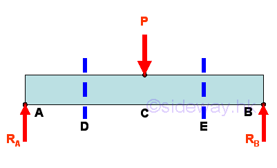
For example, ignoring the horizontal forces, dividing a simply supported beam with one concentrated load P into three imaginary beam sections.
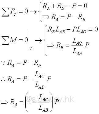
The Reaction forces can be determined by setting up the equilibrium equations. Imply
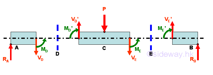
The free body diagram for the three beam sections are
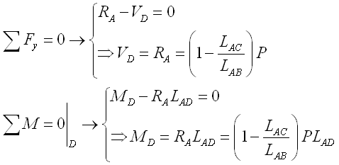
The internal forces at D can be determined by setting up the equilibrium equations of beam section AD. Imply
The internal forces at E can be determined by setting up the equilibrium equations of beam section EB. Imply
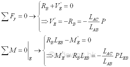
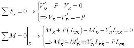
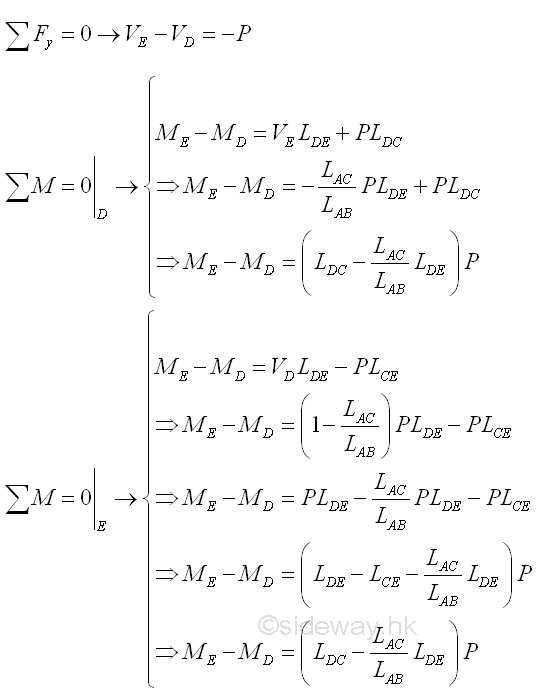
When using beam section DE as the standard convention of the difference of internal forces. The internal forces of beam section DE can also be determined by setting up the equilibrium equations of beam section DE assuming the beam is fixed at point E accordingly. Imply
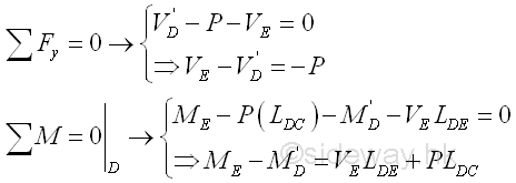
Or the internal forces of beam section DE can also be determined by setting up the equilibrium equations of beam section DE assuming the beam is fixed at point D accordingly. Imply
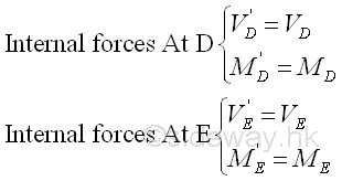
Since the sense of the internal forces are represented by the arrowheads accordingly the value of internal forces at both sides of the imaginary section plane are equal. Imply
Imply
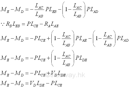
Besides, the different between the internal bending moment at point E and point D can also expressed using beam sections AD and EB. Imply
Shear in Beam
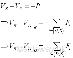
The difference of internal force, shear, between point D and point E of a standard beam section DE is equal to -P that is the shear difference is equal in magnitude but opposite in sense to the external force P. P can be the applied load or the equivalent force of all external forces.
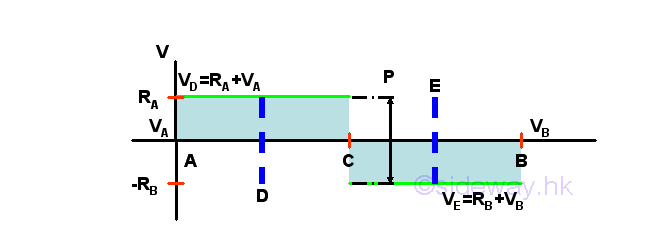
For example, the difference of shear between point A and point D of the beam section AD is equal to -(-RA) because the reaction force at point A is in opposite sense to the convention of applied force P used and therefore as VA is equal to zero, VD is equal to RA+0=RA. In normal practice, when the beam section AD is extended to C rightward, i.e. beam section AC, the shear difference is still equal to RA because the section is assumed to be fixed at point C and the applied load P is ignored in practical calculation. The applied load P is counted again once the condisered beam section exceed position C, e.g. point E and the shear difference is equal to -(P-RA)=-RB because P is greater than RA and P is in same sense to the convention of the applied force P. And therefore as VA is equal to zero, VE is equal to -RB+0=-RB.
Similarly from another end of the beam, the difference of shear between point B and point E of the beam section EB is equal to -(-RB) because the reaction force at point B is in opposite sense to the convention of applied force P and therefore as VB is equal to zero, -VE with standard convention is equal to -(-RB)-0 or VE is equal to -RB . In normal practice, when the beam section EB is extended to C leftward, i.e. beam section CB, the shear difference is still equal to RB because the section is assumed to be fixed at point C and the applied load P is ignored in practical calculation. The applied load P is counted again once the condisered beam section exceed position C, e.g. point D and the shear difference is equal to -((P-RB))=-(RA). And therefore as VB is equal to zero, -VD is equal to -RA-0=-RA or VD is equal to RA .
So for the shear curve between point D and point E, the shear curve is a discontinuous horizontal line graph with a step change of -P at point C. But for normal practice, beam secion, e.g. beam sections AC and CB is always selected between two successive external concentrated loads, the shear curve is a horizontal line becaue the step change of -P is located at the beginning of the shear curve. In short, since VA is equal to zero, the shear curve of beam section AC is a horizontal line at VC=-(-RA)+VA=-(-RA)+0=RA. And since VC is not equal to zero, the shear curve of beam section CB is a horizontal line at VB=-(P)+VC= -(P-RA)=-RB.
Shear Diagram
Bending Moment in Beam
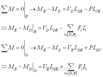
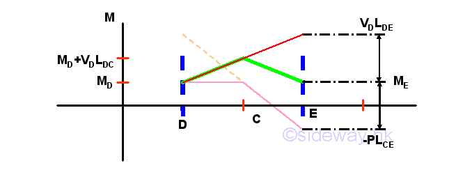
The difference of internal force, bending moment, between point D and point E is equal to VDLDE -PLCE that is a function of the external force P, the internal shear force VD and the position of point C on the beam section DE; and the lenght of beam section LDE is of couse a variable of the bending moment difference. Besides when consider bending moment, the position of the point of the bending mement taking about, i.e. point E on the right hand side is also important in applying the convention of internal forces. PLCE can be the bending moment due to applied load or the equivalent bending moment due to all external forces.
Assuming the external force P is equal to zero, the curve of the bending moment becomes a oblique straight line with slope VD over the length LDE. Assuming the internal shear force VD is equal to zero, the curve of the bending moment becomes a horizontal straight line from point D to Point C because of no acting force on the beam, and is a negative oblique straight line with slope -P from point C to point E. Therefore the curve of bending moment due to all forces is oblique straight lines with positive slope VD from point D to point C and becomes a oblique straight line with negative slope -VD(LDC /LCE) from point C to point E.
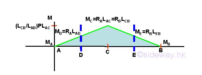
For example, the difference of bending moment between point A and point D of the beam section AD is equal to 0-(-RA)LAD because VA is equal to zero and the bending moment due to reaction forcet RA is in opposite sense to the convention of bending moment due to P and therefore as MA is equal to zero, MD with standard convention is equal to RALAD+MA=RALAD+0=RALAD. In normal practice, when the beam section AD is extended to C rightward, e.g.. beam section AC, the bending moment difference is increased to RALAC linearly only because the section is assumed to be fixed at point C and the applied load P is ignored in practical calculation. The applied load P is counted again once the condisered beam section exceed position C e.g. point E and the bending moment difference is equal to 0-(PLCE-RALAE)=RALAE-PLCE=RBLEB because bending moment of the right hand side of point E is of same magnitude and same convention to the left side with correct sign of same sense of bending moment. And therefore as MA is equal to zero, ME with standard convention is equal to (RBLEB)+MA=(RBLEB)+0=RBLEB.
Similarly, the difference of bending moment between point E and point B of the beam section EB is equal to (0+(-RB)LEB) because VB is equal to zero and the bending moment due to reaction forcet RB is in opposite sense to the convention of bending moment due to P and therefore as MB is equal to zero, -ME with standard convention is equal to -(RBLEB) or ME with standard convention is equal to(RBLEB. In normal practice, when the beam section EB is extended to C leftward, e.g. beam section CB, the bending moment difference is increase to RBLCB linearly only because the section is assumed to be fixed at point C and the applied load P is ignored in practical calculation. The applied load P is counted again once the condisered beam section exceed position C e.g. point D and the bending moment difference is equal to 0+(PLDC-RBLDB)=-(RBLDB-PLDC)=-(RALAD) bending moment of the left hand side of point D is of same magnitude and same convention to the right side with incorrect sign of same sense of bending moment. And therefore as MB is equal to zero, -MD with standard convention is equal to -(RALAD)-MA=-(RALAD)-0=-(RALAD) or MD is equal to RALAD.
So there is a change of curve slope at point C. But for normal practice, the cutting beam section i.e. beam secions AC or CB is always between two successive external concentrated loads, the bending moment curve is a oblique straight line with slope of (VD-P) at the left hand side of the beam section with standard convection. In short, the slope of bending moment curve of beam section AC is (0-(-RA))=RA. And the slope of bending moment curve of beam section CB is (VC-P)=RA-P=-(P-RA)=-RB.
©sideway
ID: 120900001 Last Updated: 9/1/2012 Revision: 0 Ref:
References
- I.C. Jong; B.G. rogers, 1991, Engineering Mechanics: Statics and Dynamics
- F.P. Beer; E.R. Johnston,Jr.; E.R. Eisenberg, 2004, Vector Mechanics for Engineers: Statics
Latest Updated Links
- Travel Singapore Sight Mandai(last updated On 12/8/2025)
- Travel Singapore Sight Bird Paradise(last updated On 12/7/2025)
- Travel Singapore Sight(last updated On 12/6/2025)
- Travel Singapore Rail Network(last updated On 12/5/2025)
- Travel Singapore Things to Know(last updated On 12/4/2025)
- Travel Singapore(last updated On 12/3/2025)
- Legrand Galion(last updated On 12/2/2025)
- Schneider Electric AvatarOn(last updated On 12/1/2025)
- Alfalux(last updated On 11/30/2025)
- Novabell(last updated On 11/29/2025)
- TownGas NJW12RM1(last updated On 11/28/2025)

 Nu Html Checker
  53
53  na
na  na
na
Home 5
Business
Management
HBR 3
Information
Recreation
Hobbies 9
Culture
Chinese 1097
English 339
Travel 24
Reference 79
Hardware 54
Computer
Hardware 259
Software
Application 213
Digitization 37
Latex 52
Manim 205
KB 1
Numeric 19
Programming
Web 289
Unicode 504
HTML 66
CSS 65
SVG 46
ASP.NET 270
OS 431
DeskTop 7
Python 72
Knowledge
Mathematics
Formulas 8
Set 1
Logic 1
Algebra 84
Number Theory 206
Trigonometry 31
Geometry 34
Calculus 67
Engineering
Tables 8
Mechanical
Rigid Bodies
Statics 92
Dynamics 37
Fluid 5
Control
Acoustics 19
Natural Sciences
Matter 1
Electric 27
Biology 1
